Air Guitar via Electromyography
Introduction and Background Info
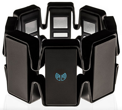
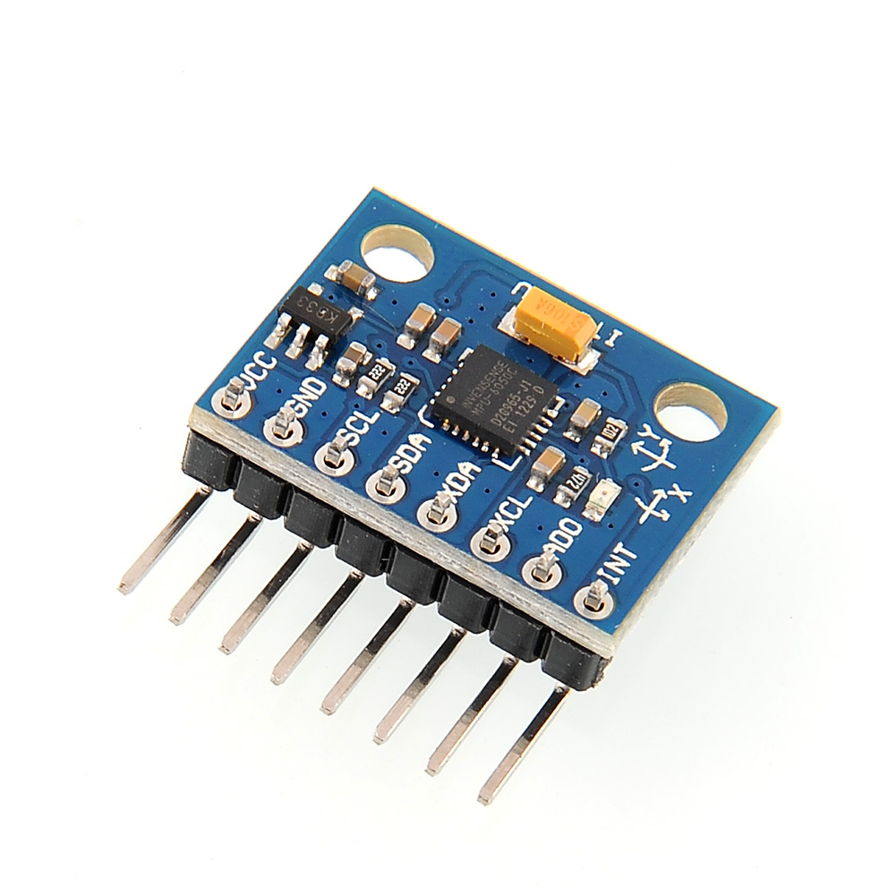
As the field of music technology progresses, modern advancements in Human Interface devices are increasingly being applied to control and composition of electronic music. The goal of this project is to utilize electromyographical (EMG) sensors and inertial measurement units (IMU) in order to develop a functional MIDI “Air Guitar”. To achieve this goal, two main devices will be used. The first is called the Myo Armband, which is a device containing 8 EMG electrodes packaged into a band worn on the forearm. The Myo also includes a microcontroller and battery, as well as an IMU to determine arm orientation. The Myo’s firmware recognizes five predefined gestures: wave out, wave in, fist, fingers spread, and rest. The Myo incudes a software API written in C++ for third party development. While the Myo provides a wealth of Human Interface options for one hand, in order to mimic the function of a normal guitar the project must include some form of sensing for the other hand. As such, the Invensense MPU-6050 IMU was selected to be worn on the other hand. This IMU provides 3 axes of accelerometer data, and 3 axes of gyroscope data. The IC is commonly used in smartphones and tablets, and its small size and low power consumption make it ideal for wearable applications.
Completion of the Air guitar project required some mechanical design of a “glove” which houses the MPU-6050 IMU, and supporting electronics required to provide output to the computer. Following this, a modular approach to software development was taken. The first module is the IMU code, written in C++ for Arduino. The second module is the C++ code to output relevant Myo IMU and gesture data so it can be converted to MIDI. The third and final module is the max patch which receives data from both previous modules, and creates MIDI output based on the data.
Strum Sensor
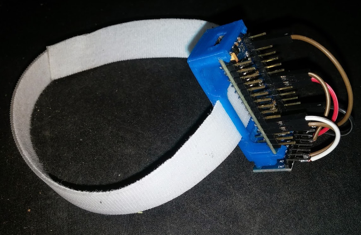
Since the left hand “chord” gestures and fretboard position are determined by the Myo Armband, the strumming motion of the right hand is detected by the MPU-6050 connected to an Arduino Nano microcontroller. To securely mount these board to the right hand, a bracket was 3D printed and attached to the back of the hand via a Velcro strap. The image below shows the finished bracket with the Arduino and MPU-6050.
The MPU-6050 is rigidly attached to the end of the bracket using mounting holes in the PCB. This method of mounting ensures that the IMU cannot move with respect to the user’s hand during use, which is important since any motion would produce erroneous acceleration measurements. The IMU is also mounted as far from the wrist as possible, since most strumming motion occurs at the end of the hand. The Arduino is clipped into the bracket, and is easily removable for upgrades or for easier programming. The mini-USB port fits in a cutout in the bracket, which holds the connector securely during operation. A wireless version of the strum sensor was designed, using the ESP8266 IC to achieve TCP/IP communication. Unfortunately, the added mass of this IC and the batteries to power it would make the sensor cumbersome to wear.
Software Development
The Arduino software was written in C, using the MPU-6050 libraries developed by Jeff Rowberg. The sketch determines if the MPU-6050’s Y-axis accelerometer value was outside of range, and sends a serial message if it was out of range with some smoothing. The signal was conditioned such that the software would only send one serial message per strumming motion.
The Myo code was developed in Microsoft Visual Studio 2013 in C++. The software uses the Myo libraries to ascertain which gesture is being made. After mapping the gesture to a MIDI note number, and scaling it according to the user’s hand position on the fretboard, the midi note number is packaged into an OSC message, and sent to the Ethernet loopback port via UDP. The Myo IMU’s yaw value was analyzed in order to determine fretboard position.
Finally, the serial data and the UDP package are read by a Max patch, which sets the noteout message according to the MIDI note number specified by the Myo gestural input. When serial data is received on the Arduino port, the max patch sends a bang to the noteout object, triggering the appropriate MIDI note. The MIDI output is sent to a virtual loopMIDI device, which can be read by Ableton Live or other MIDI software.


